JobWizard Utility
The Job Wizard software allows creating and editing the microarray print jobs. Print jobs recorded to the database serve as instructions for the spotter control software - JobControl.
Step 1. Job Name Selection
Start creating the print job with a name that later will be used to start the spotter to execute this job.
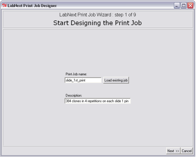
The Job Wizard prompts to save the new name in the database before moving to the next screen in the wizard. Later this name can be used for searching and editing the print job. Once an existing job is edited it can be saved under the current name or under a new name at the last step of the Job Wizard.
Step 2. Microplate Specification
At the second step the Job Wizard requires to specify parameters of the microplate that will be used for printing. Dimensions of micro plates of different vendors may vary significantly. It is necessary to take measurements shown at the drawing below or to find the dimensions using vendor's specifications.).
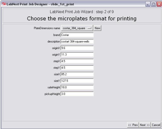
The
measured parameters have to be entered in the form at the step 2 of
the Job Wizard and saved under a unique name (COSTAR_384_PCR for
example).
Once measured and registered the micro plates can be used in the print jobs in the future by selecting the relevant name. Their geometrical parameters will be automatically fetched from the database.
Step 3. Registering Plates Content. Selecting Source Plates for the Microarray.
At this step positions of the DNA clones in the source plates are being registered. Open the plate image form by pressing the <New Plate Content> button. Pressing the <New Plate Layout> button initializes a 384-wells plate with all wells empty. An empty well must be marked by the "EMPTY" string and will be ignored by the spotter. Any other string, even the blank one will be considered as a clone name by the software and the corresponding well as containing a clone.
When printing with more than one needle the spotter may sink needles in empty wells. Sometimes if the microplate has been filled with a multi-channel instrument, some wells may contain only the printing buffer with no DNA in it. Needles will be leaving spots on the substrate surface with close to background intensity. These spots will not be annotated.
It is makes sense to annotate filled wells with the name of the clone in them.
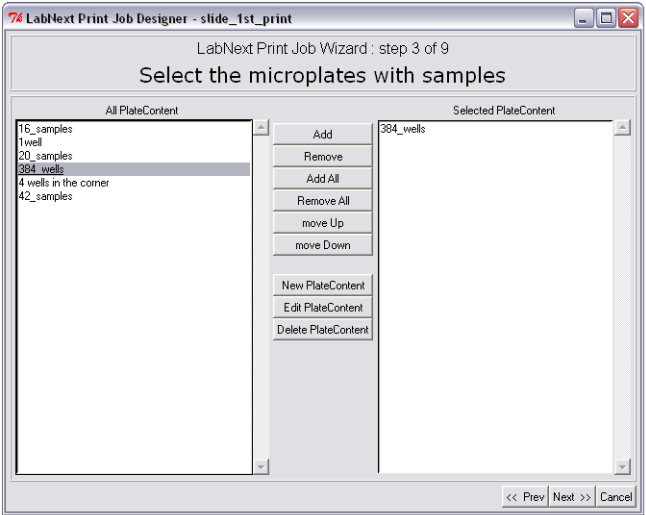
In order to select microplates that will be used in this print job from the available microplates it is necessary to mark them in the left panel "All Plate Content" and pressing the <Add> button move them to the right panel "Selected Plate Content". All DNA clones from the plates listed in the right panel will be printed on the microarray. The <Remove> button excludes selected microplates from the print job but not deletes them from the database. If there is more than one microplate assigned for the print job the spotter will be stopping in order to replace microplates that have printed with the new ones. The spotter will print microplates in the same order they listed in the right panel "Selected Plate Content". Pressing the <move Up>, <move Down> buttons allows to change the order of microplates in the window and therefore the printing sequence.
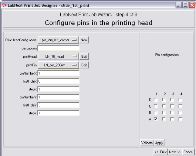
Step 4. Printing Head Configuration.
The configuration deals with specifying head type, printing needles type and their positions in the head. Although it is possible to edit geometrical specifications of printing heads and needles form this program it is not recommended. There is a special program named "Configure System" designed specifically for registering all tools and configuring the system before the operations.
Each printing head configuration can be saved under a unique name by pressing the button next to the "PrintHeadConfig name" label. Similar buttons next to the "printHead" and "printPin" labels open lists of heads and needles that have been registered already in the database.
The number of needles and their positions in the head can be edited in the right part of the "Pin Configuration" window. On the 4x4 head pattern it is necessary to mark the check boxes that correspond to the positions of needles in the real head. The <Validate> button initiates configuration validity check. A number of asymmetrical configurations not allowed and the system will generate the error message in case eon of them has selected.
The <Apply> button registers selected head configuration in the database. The numeric fields in the left part of the window change their values according to the logic of selected configuration.
Step 5. Design of Microarray Pattern.
It is recommended to pay extra attention to this step because positioning of spots on the chip affects quality of the following hybridization and scanning. It is an expedient approach using one and the same microarray pattern for a logically linked series of experiments. This can significantly improve data consistency.
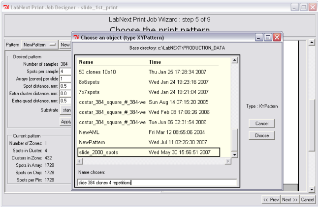
Chip patterns can be saved in the database under unique names and reused later for another microarrays. In order to select a pattern that's already saved in the database it is necessary to click the button next to the <Pattern> label. Patterns do not depend on the DNA clones suppose to be printed on the microarray it is just a template to deposit them.
The program allows designing microarray pattern in the semi-automatic and manual modes. The semi-automatic mode is the default one. The <Advanced> button starts the manual mode.
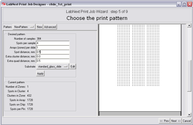
In order to specify microarray pattern it is necessary to fill out the fields in the "Desired Pattern" panel. Please refer to the Microarray Geometry section of this manual for information regarding terms the microarray pattern is decribed.
-Number of Samples - not editable. Shows the total number of clones form all plates assigned for printing in this job.
-Spots per sample - number of repetitions for each clone. Duplicates of spots can be used for controlling data repeatability in the experiment.
Arrays (zones) per slide - number of identical arrays on one substrate. Arrays will be placed along the vertical (long) side of the substrate.
-Spot distance mm - spacing between spots measured in millimeters.
- Extra cluster distance mm - distance between clusters OVER the minimal distance that keeps clusters from overlapping.
- Extra quad distance - distance between quads OVER the minimal distance (that is equal to distance between the needles)
The last two parameters limit maximum allowed spots in the pattern. It makes sense to set them more that 0 only in case of the risk of spots merging during the printing of microarrays.
Enter 0 value in these fields to let the program design the optimal pattern automatically. The pattern will be created based on the following principles:
- The work surface of the substrate is logically divided into identical rectangular areas equal in number to the number of zones (arrays) suppose to be printed on the substrate. Each array will be printed in geometrical center of the corresponding zone.
- Each cluster of spots will be printed in 1xN pattern (as a horizontal line).
- Extra quad distance will be set to maximum value that allows to accommodate all required spots on the array.
Save the pattern after selecting all parameters. Once saved the pattern can be used in other print jobs by selecting its name from the list of available patterns.
Registering and Editing Parameters of Substrates.
Clicking on the <Edit> button right form the "Substrate" label opens the substrate parameters window.
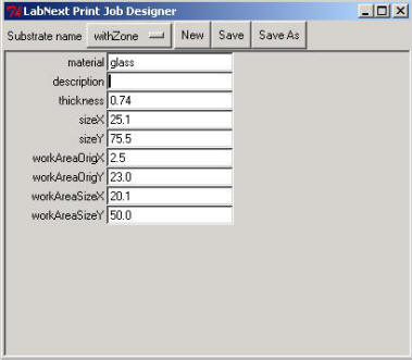
Meanings of the fields are:
- material - material that the substrate made out. (glass, nylon, etc.)
- description - free format description. Non-mandatory field.
-
thickness - substrate thickness
The rest of parameters explained at the picture below.
It is possible to save parameters of substrates in the database and use them just selecting an appropriate name without editing the parameters before each printing.
Step 6. Design of Prespotting Pattern.
Prespotting is the deposition of a number of spots on a designated substrate (prespotting substrate) in order to remove excessive liquid from tips of the needles right after sample pick-up. Number of prespotting spots depends on the type of the needles, material of the substrate, viscosity of printing buffer and environmental conditions - temperature and humidity. For the LabNEXT composite capillary needles this number ranges from 1 to 6. In case of using a new printing buffer, other than the LabNEXT printing buffer it is recommended to make a few test printing runs in order to determine the number of prespotting spots require. Editing of prespotting patterns is totally identical to editing the microarrays patterns.
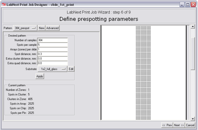
Main criteria for designing of prespotting patterns though differ form ones used for microarrays patterns. It is recommended to by guided by the following principles:
- Use minimal possible number of prespotting spots in order to save space on the prespotting substrates.
- It is possible to reduce the distance between spots in comparison to the distance between sports in microarrays and allow spots merging WITHIN ONE CLUSTER. A cluster consists of spots with one and the same clone therefore there will not be risk of contamination with adjacent clones.
- Clusters must not merge. To prevent them from merging set the Extra Clusters Distance to a >0 value.
- Try to use fully the surface of prespotting substrates.
- One and the same prespotting layout can be used in many print jobs.
Step 7. Placing Substrates on the Work Board of the Spotter.
Substrates can be placed in any slide nests in any order. Press the button in the lover part of the image of a slide nest to register positions of the glasses on the board. Register all substrates in the way they are placed on the work board. The spotter prints starting form the right lower substrate clockwise. It is better to put prespotting substrates in the first positions on the printing path. Empty positions will be ignored. If there are not enough prespotting substrates to accommodate all prespotting spots the print run will be suspended and the spotter control software will generate the message prompting to replace prespotting spots.
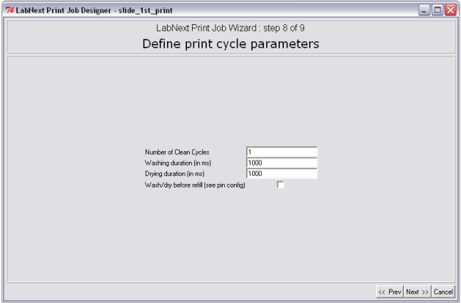
Step 8. Definition of Print Cycle Parameters
Besides deposition of the spots on the substrates print cycle include a few other actions such as washing and drying and refilling of the pins in case they run out of the liquid.
Washing and drying routine is intended for cleaning of the pins between samples pickup in order to prevent cross contamination of the samples. Every printing buffer and molecules require different parameters of cleaning. At the step 8 of the JobWizard it is possible to define:
- Number of clean cycles from 1 to any number. If the number clean cycles is more than one the microarrayer would repeat washing and drying routine multiple times.
- Washing Duration. This parameter defines the time pins stay in the washing chamber of the wash/dry station. The parameter is defined in milliseconds. 1000 ms = 1sec.
- Drying Duration. This parameter defines the time pins stay in the dryer. The parameter is defined in milliseconds. 1000 ms = 1sec.
For most of the water based printing buffers one clean cycle is enough for proper decontamination of the Xtend microarray pins. Typical washing and drying times vary from 3000 to 6000 ms (3-6 seconds).
Using buffers with high viscosity or buffers with high adhesive properties may require longer washing and drying time and more that one washing/drying cycles.
- Wash/dry before refill parameter defines whether the pins are leaned or not when refilling with the same samples. Refill parameters are entered as the properties of the pin at the step 4 of the JobWizard.
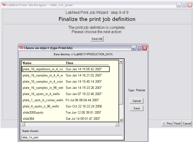
Step
9. Saving Print Job.
Clicking the <Save Job> button can save print job. If there are unsaved changes the program will prompt to save the job before finalizing the Job Wizard.
Print Job Execution
The newly created print job can be executed using the JobControl utility. Please refer to the JobControl section of this manual for instructions.