Application Manual for Xtend Microarray Pins
Detailed pins specifications can be obtained online at www.labnext.com/xtend.htmlPrecautions
80um and 100um Pins Extra Precautions Needed
- Tips are extremely fragile. - Do not touch tips by hand. - Do not drop pins. - Try to minimize lateral forces applied to the pin tip. - FILTER all liquids used for printing and cleaning the pins. All other precautions are also apply to 80um and 100um pins.140um through 700um Pins
All parts of the Xtend pins a rigid and resistant to chemical, mechanical and temperature weariness. However certain precautions must be taken to keep the pins from damage, extend the operation life and achieve best results in printing microarrays. The ceramic tip can be broken if it is bent with significant force or the pin is dropped on a hard surface. When handle and operate pins consider the tip made of glass, with such a treatment the tip will be safe from breaking. - The capillary channel of the pin is very thin. It can be clogged with small particles contain in the printing liquids or in the air. - Always use filtered liquids for printing. Example of filters: http://www.daigger.com/store/syringe-filters-30-mm8439y1/18893?section=20 - Store pins in clean environment - Avoid touching tips by hand. - The capillary channel of the pins can be clogged with salt crystallized if printing solution left in the pins and dried out. - Always wash and dry pins after printing either manually or in the microarrayer. - Do not heat pins over 120 C.Operations
We recommend start with using pins of larger diameters first to get enough practice and then go to the smallest diameters. The pins of larger diameters have wider capillary channel and less sensitive to contaminants such as dust or other particles that can clog the channel. They are also easier to clean. Ideal pin size to start with is 0.3mm Always be sure that capillary channel is clean before using the pin. If capillary channel is clogged the pin will not pick-up liquid. To check the pins use a syringe with a thin dispensing tip. Insert the tip into the metal part of the pin and try to blow air through it. If the air goes thought the pin the capillary channel is free. If not the pin requires cleaning before use. Keep the pin clean after use. If the printing buffer or printing material is left and dried on the surface of the pin, next time it will be producing inconsistent spots until the residue is dissolved and washed away.Cleaning
For cleaning in the course of normal printing operations dip pins into cleaning solution for 4-5 seconds to allow pins to pick-up maximum amount of liquid. Dry pins in a drying station that allows blowing air through the inner channel of the pin. Typical cleaning solutions for microarray operations are distilled water or 10% alcohol. For printing with other substances choose cleaning agent that can dissolve such substances. For cleaning pins with clogged channels use stronger solvents. 90% alcohol or acetone can be used for cleaning pins. Some times boiling pins in water allow dissolving particles that block the capillary channel. When boiling isolate the pin from the bottom of the boiling reservoir. Use ultrasonic cleaner. If necessary, use syringe with a dispensing tip attached to blow air or washing liquid through the pin to clean the capillary channel. You can blow air both ways through the pin. See the image below.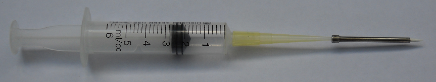
NOTE: Do not do this with 80um and 100um pins. You will most certainly damage the tip.
Basic Troubleshooting
Visual observation ( under a microscope or a visible light scanner ) may not show features otherwise detectable in wavelengths of fluorescent scanners. Visa versa, some times visible light observation shows artifacts in printing that will not appear in the scanners or may disappear during microarray processing. However for the purpose of this manual we used visual ( paper ) scanner at 2200 px/inch resolution to indicate and discuss most common undesirable patterns that may occur in microarray printing. Microarrays were printed on plain glass slides with water based blue dye solution. Spot size is 140um, distance between spots is 230um. Ideally microarray spots should appear uniform after printing. Uniform means equal in shape, size and even distribution of the printed material across the surface of the pin.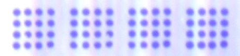
"Doughnut" spots.
"Doughnut" spot results from a splash, a "vortex ring" ( or "toroidal vortex" ) in the deposited liquid if the pin hits the surface at a high speed. The speed when the pin leaves the surface of microarray substrate is equally important. More about Vortex Rings - http://en.wikipedia.org/wiki/Vortex_ringIn order to produce the doughnut shaped spots shown on the image above we intentionally increased vertical speed of the microarrayer ( approximately 50% to the speed at which it did not produce doughnut spots). If the liquid is viscous enough and to keep the shape for a second or so, the liquid dries out and leaves the spot in the shape of 2-D projection of the ring. We do not recommend any particular "optimal" speed that would prevent formation of the doughnut spots because the process also depends on the physical properties on the microarray buffer, such as viscosity and surface tension and on the hydrophilic properties of the substrate surface.
Reduce vertical speed
First remedy against the doughnut shaped spots is reducing vertical speed of the microarrayer when the microarray pin approaches the surface of the substrate and leaves it. However some microarray systems ( with stepper motors ) may move in fast increments that are not controllable. Although average vertical speed may be low, the movement consists of a series of fast downward steps and when the pin hits the surface it moves too fast. For such microarrayers with a relatively big steps controlling vertical speed is not an option.Adjust printing buffer composition
Adjusting physical properties of the printing buffer is another way of dealing with the doughnut shaped spots. You can slightly increase viscosity of liquid (for example adding glycerol to water based buffers). Glycerol - http://en.wikipedia.org/wiki/Glycerol Higher viscosity will reduce mobility of liquid and therefore prevent "splashes" at deposition. Another approach is decreasing surface tension of the buffer. Usually this is achieved by adding small amount of detergent ( SDS for example in the magnitude of 0.1 - 0.01% ) to the buffer. SDS - http://en.wikipedia.org/wiki/Sodium_dodecyl_sulfate Lower surface tension changes spots shape - typically a hemisphere, making it lower ( "flatter" ). Lower surface tension also eases detachment of the droplet from the pin tip when the pin moves up.Printing with Non Filtered Solution.
The image below is a typical example of printing with a buffer that contains floating particles. In order to produce it we did not filter the buffer after dissolving the blue dye in it. A portion of the dry dye did not dissolved and left in the form of small floating particles. Particles partially block capillary channel causing variations to the amount of liquid delivered in the spots. They also tend to form conglomerates within the spots perimeter, and often cause spots to change shape and even move sideways after deposition.In general random looking uneven features in the spots is an indication that small solid particles are present in the buffer. Such a buffer should be filtered using filters described above on this page. Example of filters: http://www.daigger.com/store/syringe-filters-30-mm8439y1/18893?section=20
Printing on Non Uniform Surfaces.
Non-uniform surface of a microarray substrate can be a cause for non-uniform spots. Often variations in the surface properties can not be observed prior to printing. Appearance of repeated similar features in a number of spots is an indication that the surface of the microarray substrate may have a defect. In order to produce the microarray below, the glass slide was wiped in vertical direction with a tissue soaked in acetone. Although it is left no visible trace, the spots printed on the surface in the left - middle part of the microarray feature similar blank areas in the shape of vertical stripe.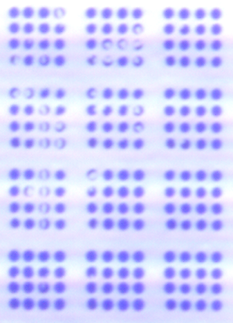
Measuring and Controlling Deposition Volume.
You can not explicitly control deposition volume for a pin. You need to use a different pin if you want to print bigger or smaller spots. Moreover for each pin - buffer - surface combination deposition volume may vary. It is advisable to measure deposition volume delivered in each spot in your particular environment. (Table we provide on the website www.labnext.com/xtend.html is for distilled water - plain glass combination, which my be very different if you are using viscous buffers or absorbing substrates ) To measure deposition volume we recommend loading the pin manually from a lab pipette ( 0.1 uL ) to be sure that all this liquid is inside the pin tip. Then print as many spots as necessary until the pin runs out of liquid. Divide 0.1uL by the number of spots printed and you will have a fairly accurate estimate of each spot volume. For 1nL the should produce about 1000 spots out of 1uL load. There is a way of controlling deposition volume for absorbing surfaces such as porous membranes ( nitrocellulose ). Such a material can absorb fairly large volume of liquid over a time interval. The longer pin stays in contact with the the surface the bigger volume is absorbed. Thus regulating contact time of the pin tip with the substrate gives ability to control deposition volume. As mentioned above every buffer - surface type combination produces different results. Experiments should be conducted to estimate the actual deposition volume and its dependency from the contact time. Non absorbing surfaces, such as some plastics, glass or metals do not demonstrate significant dependencies of the spotting volume from the contact time.Dimensions Reference for Xtend Microarray Pins (Version 2.0).
NOTE: Version 2.0 Xtend pins are available since 10.2017. V2.0 replace V1.0 and fully compatible with all LabNext print heads and have equivalent performance in every aspect. Key dimensions of V1.0 and V2.0 are the same. However there are a few minor differences between the two versions. - V2.0 pins have slightly longer collar ( upper , wider part ) - V2.0 pins have differently looking metal surface due to a new manufacturing technology. Specs for the V1.0 version of Xtend and Xtend RM pins can be found here: www.labnext.com/documents/images/pins_manual/xtend_v1.png