Setting Xact Microarrayer for Microplate Printing.
In order to set the microarrayer for microplate printing it is necessary
to replace the Slide Holder with the Microplate Holder (LabNEXT p/n 110) and
change the software settings that describe geometry of the printing substrates.
Lab Next plate holder for Xact microarrayer accommodates two microtiter plates
so the number of substrates must be set to 2 substrates instead of 14 for slide
printing. The size of substrates must be also altered to the size of the
microtiter plates.
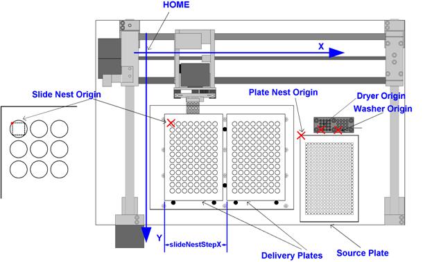
After setting parameters of the substrates it is necessary to specify
the new <Slide Nest Origin> and the spacing between the plates <slideNextStepX>. Other reference points on the
microarrayer work board (Plate Nest Origin, Dryer Origin, Washer Origin ) remain the same.
After performing the actions described above it will be possible to
specify print jobs using the Job Wizard program.
Register
a new configuration of the microarrayer.
-
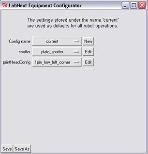
Run ConfigureSystem program.
-
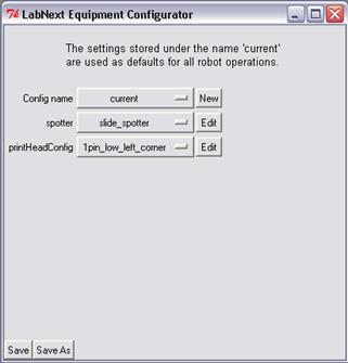
- Click [Edit] button next to the <spotter> title in the “LabNext
Equipment Configurator” dialog.
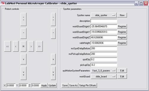
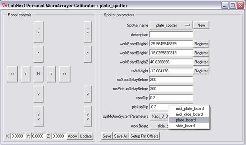
- In the opened “LabNext Personal Microarrayer Calibrator” dialog click
on the [Save As] button.
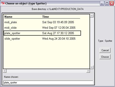
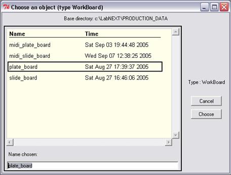
- In the opened dialog “Choose an object (type Spotter)” type in the
<Name chosen> field type: plate_spotter and press [Choose] button in the right side of
the dialog window.
-Close the “LabNext Personal Microarrayer Calibrator” dialog window
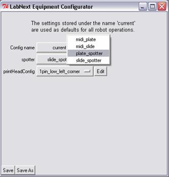
- Get back to already opened “LabNext Equipment Configurator”
dialog and click on the button next to the <spotter> string. In the
opened drop-down list select <plate_spotter>
entry.
- Press [Save] button in the low left corner of the “LabNext Equipment Configurator” dialog window.
- Click [Edit] button next to the <spotter> title in the “LabNext
Equipment Configurator” dialog. This will open
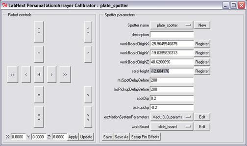
‘LabNext Personal Microarrayer Calibrator” dialog. Please check if the the opened dialog refered to the plate_spotter.
(<Spotter Name> string in the right panel should indicate plate_spotter).
-
Insert a pin into the far-left hole of the print head.
x o o o
o o o o
o o o o
- Install Microplates in the
plate holders.
- Press [H] button in the
center of the “Robot Controls” panel. Wait till robot performs homing
operation.
- Using arrow buttons at the
“Robot Controls” panel move the tip of the pin 1-2mm over the highest object on
the work board and click on the [Register] button next to the <safeHight> string at the “Spotter parameters” panel.
- Press [Save] button in the
bottom of the “LabNext Personal Microarrayer Calibrator” window.
- Press [Edit] button next to <workBoard>
string in the right panel “Spotter parameters”. This will open the “WorkBoard Editor” window.
- In the “Work Board editor” window press [Save As] button.
- In the opened “Chose an Object (type WorkBoard)”
dialog type plate_board in the <Name Chosen> field.
- Click on the [Choose] button in the left part of the dialog window.
- Return to the opened “LabNext Personal Microarrayer Calibrator”
window.
- Click on the button next to the <workBoard>
string. From the drop-down list select the plate_board entry.
- Click on the [Save] button at the bottom part of the “LabNext Personal
Microarrayer Calibrator” window.
- Press [Edit] button next to <workBoard>
string in the right panel “Spotter parameters”. This will open the “WorkBoard Editor” window.
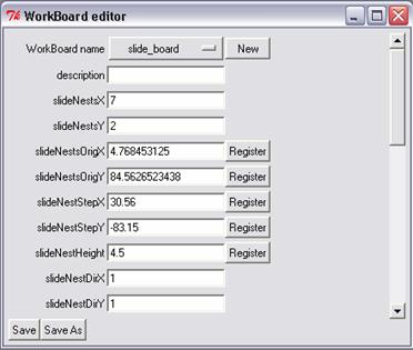
- Please ensure that plate_board is
indicated on the button next to <WorkBoard
name> string at the very top of the “Work Board editor” window.
- Set <slideNestsX> = 2
- Set <slideNestsY> = 1
- Set <slideNestStepX> = 92.35
- Set <slideNestStepY> = 0
NOTE: slideNestStepX = 92.35 mm for plate holders manufactured by
LabNEXT. In case of using self made holders please take a measurement in
millimeters of the distance between the left edges of the microplates and use
this measurement as a value for <slideNestStep>
variable.
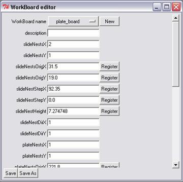
- Using manual controls move the pin to the upper-left corner of the
upper-left well of the left microplate
- Press [Register] next to <slideNestOriginX>
string
- Press [Register] next to <slideNestOriginY>
string
- Remove the microplate from the holder and using the manual controls
touch with the tip of the pin surface of the plate holder.
- Press [Register] next to <slideNestHeight>
string
- Scroll to the bottom part of the “WorkBoard
editor” window.
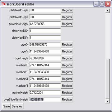
- Using robot manual controls move the pin tip 1-2 mm over the delivery
plates.
- Press [Register] next to <overSlideNestHeight>
string
- Click on the [Save] button at the bottom of the “WorkBoard
editor” dialog.
- Close the “WorkBoard editor” dialog window.
- Please ensure that plate_spotter is
indicated under the current configuration
at the “LabNext Equipment Configurator”
- Close “LabNext Equipment Configurator”
dialog window.
This ends the setting of the system configuration for microplate
printing. After that configurations can be toggled between plate and slide
printing just by changing the <spotter> parameter.
Setting
Substrate Parameters and Creating a Print Job for Printing in a 96-well Microplate.
- Start JobWizard.
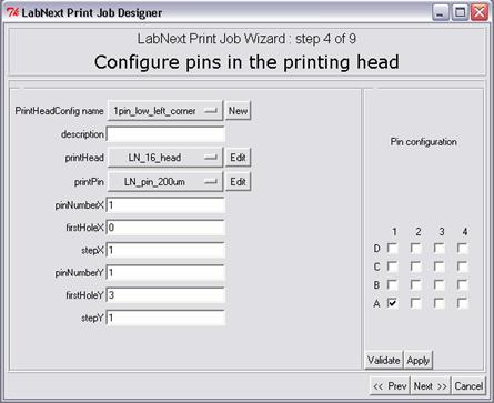
- At the Step 4 “Configure Pins in the Printing Head” please ensure that
configuration used for printing with one pin.
- At the Step 5 “Choose the print pattern” click
on the button next to <Substrate> string.
- In the opened dialog “Substrate Name” click at the [New] button and
register a new substrate with the “96 well plate” name.
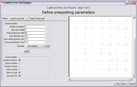
- Enter parameters of the plate as shown at the screenshot below.
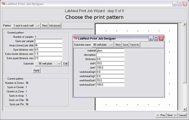
-
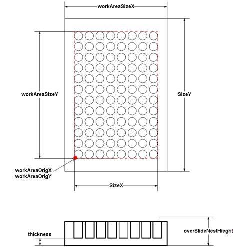
Parameters entered above correspond to the standard
96-well microplates. In case of using non standard plates take the measurements
as shown on the drawing below and use them for the settings.
Setting
Sample Print Pattern
The sample print pattern specifies printing one spot in each well of the
96-well plate. CLUSTER in the sample
pattern contains only one spot <spotsInClusterX> = 1 and
<spotsInClusterY> =1. More complex patterns can be derived from the
sample pattern by changing parameters in the CLUSTER the same way it is done
for printing microarrays on glass substrates.
- At the Step 5 “Choose the print pattern” click on the [Advanced]
button.
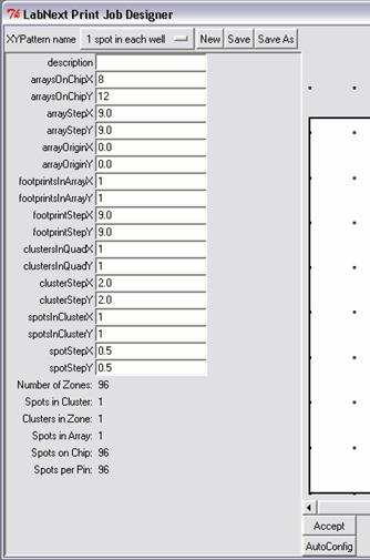
- Set <arraysOnChipX> = 8 <arraysOnChipY> = 12. This
corresponds to 96 wells. In each well the spotter will form identical array.
- Set <arrayStepX> = 9 and <arrayStepY> = 9. Those settings
correspond to the spacing between wells of 96-well plates.
- Set <arrayOriginX>=0 and <arrayOriginY>=0. The spot with
these settings will be printed in the corner of a quad inserted in the round
well as show at the picture below.
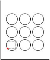
Making values of the <arrayOriginX> and <arrayOriginY>
positive will move the point towards center of the well to the left and higher
correspondingly.
- FOOTPRINT and QUAD parameters are irrelevant since the printing is
done with one pin.
- Save the sample pattern under the name of 1 spot in each well
- At the Step 6 “Define prespotting parameters” choose the same pattern
as for printing 1 spot in each well and
the same substrate 96 well plate
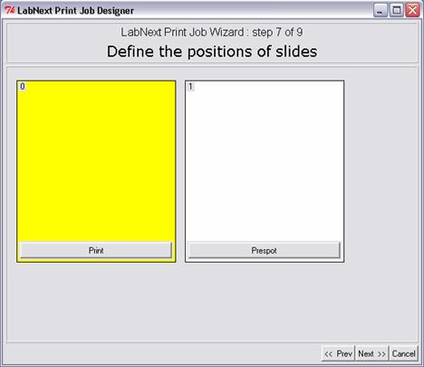
- At the Step 7 “Define the position of the slides” two substartes must be displayed on the print board. Choose one
for prespotting and one for printing. Typically LabNEXT pins don’t require more
than 1-2 prespotting hits. The “prespotting” plate therefore can be used for
real printing.