QUICK START
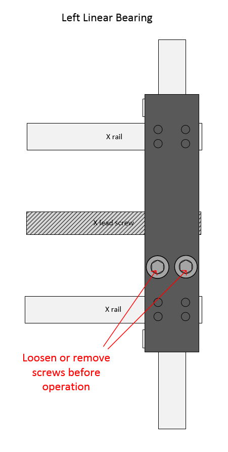
- Unpack the microarrayer. - Remove plastic wrap from the cabinet. - Install the door handle on the cabinet. - Replace srews on the door hinges with levers.- Remove soft foam protection tubes from the rails of the motion system. - US made systems, serial numbers start with E are equipped with screws locking the right side of the X axis during transportation. The screws need to be losened or completely removed before operation.
IMPORTANT After the foam tubes are removed, the motion system can be moved by hand. If you need to move it by hand, apply force to the Left side of the motion system Y axis ( front - back movements). X axis ( left-right ) can be moved by applying force ner the X lead screw. Do not apply significant force to the Right side of the Y axis of the motion system. If you need to ship the arrayer put the foam tubes back, preventing the motion systems from moving during transportation.
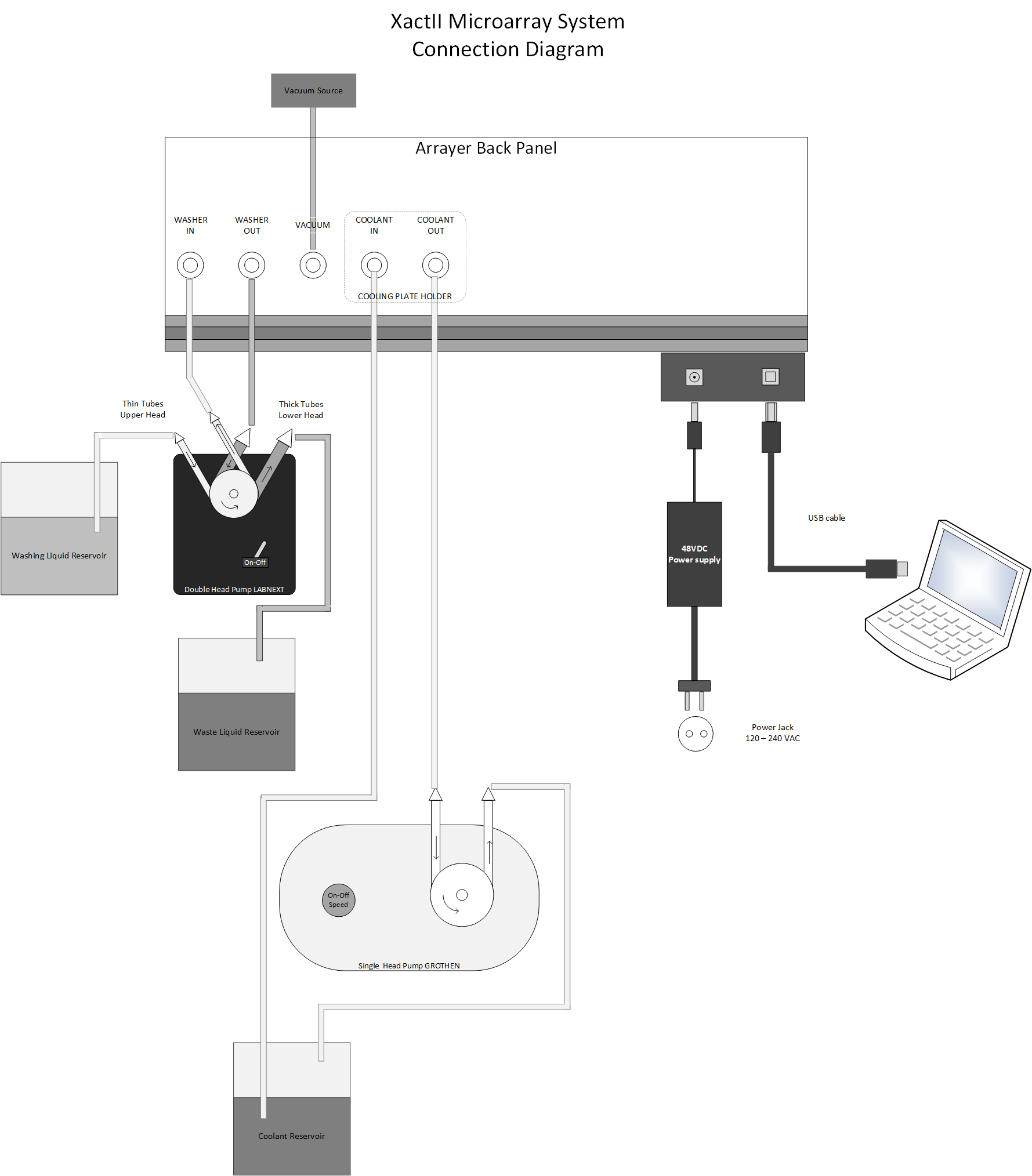
- Visually inspect all items for damage may occur during transportation. Report damage to LabNEXT ( support at labnext.com ) and to the carrier. - Install the system on the lab bench or table. The place should be equipped with 100-240 VAC power jack and vacuum source either form central vacuum tube or portable vacuum pump.Computer and Electric Connection.
Refer to the Connection Diagram for Electric and Water Tubing connection. ( Click on the image to expand. )
IMPORTANT Microarrayer power supply is 48 VDC. Do not use it with any other electronic equipment ( laptops, water pump, humidifier ). It will damage other equipment. Power supply for water pump is 12 VDC ( for LabNext pump) or 24VDC ( for Grothen pump ). Power supply for Humidifier is 12 VDC.
- Install the control software on the PC that will be working with the system. Please refer to the Software Installation section of this manual. - Connect the microarrayer power supply connector to the recepticle on the back side of the microarrayer. - Plug the cord of the power supply in the power jack. - Connect the USB cable included in the package to the USB port of the PC and to the USB connector of the microarrayer.IMPORTANT Do not connect or disconnect power supply connector +48VDC from the microarrayer when the system is in operation. If this happens you may need to restart the microarrayer controller or restart the PC. There is no ON/OFF switch on the microarrayer or its power supply. The system can be stopped from the PC by pressing Ctrl-C combination of the keys at any time. It is also possible to disconnect the power supply from the 110 - 240 VAC power outlet when the system is running.
First Run
Run the ManualControl utility by clicking on the iconIn the LabNEXT Manual Control dialog click on the [H] button in the center.
The microarrayer should lift Z ( vertical ) axis and start moving towards far left corner of the work board axis. It comes to stop after finding the Home position. Clicking on the buttons with arrows allows moving the microarrayer manually in the directions showed on the buttons. One arrow [>] indicates slower movements, one step per click. Two arrows [>>], faster movements 100 steps per click. If the microarrayer moves in all directions controlled manually and finds the Home position, it connected correctly.
Launching Pre-defined Print Routines
Launch one of the pre-programmed print routines to check that calibration of the system have not changed during transportation. Launch the JobControl utility by clicking on the iconIn the
dialog press the Load Existing Job button to select print job slide_1_spot_on_each_slide if you are printing on glass slides or plate_1_spot_in_corner_wells if you are printing in 96-well microplates from the list of the pre-programmed print jobs. NOTE: Do not insert microarray pins into the printing head of the spotter for the first run. If the calibration was lost during transportation the microarrayer can damage the pins. Run selected print job following the prompts. Observe microarrayer movements till the system stops and the Command Prompt window (black window) disappears from the screen. Put substrates (either slides or microplates) into the substrate holders of the system Insert one pin ( calibration pin ) in the left closer hole of the printing head Run the same print job again. Observe the arrayer performs two washing and drying cycles in the beginning of the print routine. Check if the pin correctly access the holes of the washing and drying station. The pin should go inside the washing reservoir through the center of the hole without touching the walls. In the hole of the dryer the pin should go till its conical part is fully inserted in the smaller inner hole. After performing washing/drying cycle the microarrayer should perform pickup from the source plate and deposition of the samples on all substrates. In case of the glass slide configuration the microarrayer deposits one spot in the center each substrate. In case of microplate configuration running the print job plate_1_spot_in_corner_wells the microarrayer should deposit samples in the centers of four corner wells of two 96-well microplates. If the microarrayer correctly moves to all points, it's ready for operation. You can use predefined printing routines or design your own using the JobWizard Utility. If it misses washing station or labware with significant errors it requires calibration which can be done using the Configure System utility. Please refer to the System Calibration section of this manual or contact technical support (support at labnext.com) for assistance.